Each hydraulic system in its equipment has valves that perform various functions and roles. In power hydraulics, an indispensable element of equipment is an overflow valve, otherwise known as a safety valve and a check valve, whose task is to protect the hydraulic pump. Other hydraulic devices operating in the system are responsible for controlling and adjusting the parameters. A very important task of such devices is to control the nature of the flow, as well as control its direction and movement of the receivers. There are three types of hydraulic valves, which are most often found in hydraulic systems - these are pressure, direction and flow control valves.
 |
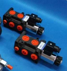 |
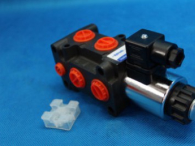
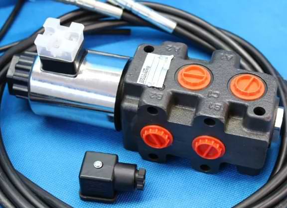
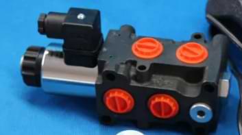
Hydraulic diverter valve is a valve that controls the pressure in the hydraulic system. The switching valve consists of two basic elements, namely an electromagnet and a hydraulic part.
The diverter valves are used in various types of timing gear - they can be found in timing belts with toothed belt or chain. These valves are mounted directly in the cylinder head and are integrated into the oil circuit. The switching valves are responsible for controlling the switched elements of the engine (usually in two stages, although liquid systems are also available). The operation of the switching valves is monitored by an engine controller which analyzes various parameters such as engine speed, operating temperature and engine load.
When talking about a two-stage control system, pay attention to how it works. The diverting valves have an electromagnet and a hydraulic part. When current flows through the valve, oil is pumped from the oil pump to the switching mechanisms. When the switching elements are unlocked, the oil passage from the pump is opened. In time when the current doesn't flow, the last passage is closed, as a result of which oil under low pressure flows into the oil sump. The time at which individual switches are made depends on the valves and the characteristics of the hydraulic circuit.
 |
In addition to the two-stage control system, there is also a stepless system that is used in newer designs. In an electrohydraulic control system, the activation of the switching valves is a two-step process. At first stage, a low current flows through the valve - its task is to pre-magnetize the valve without starting it. High current is not applied until the valve is switched. This solution allows for quick and precise work of the system. The motor controller is responsible for the correct moment of valve switching, which task is to gather information about its current operating conditions.
12 volt hydraulic diverter valves can be found in the phase change systems of the engine inlet, outlet or both. Thanks to the operation of the valves, it is possible to reduce fuel consumption as well as increase the power of the power unit. This is possible by adjusting the gas exchange in the cylinders to the current operating conditions of the engine.