Electronic regulator for double solenoid proportional control valve
 |
 |
Working description
The VPUD-M electronic regulator is designed to command two proportional solenoids with one reference signal. Solenoids are controlled (PWM) with feedback signal so that linearity between output current and input signal is guaranteed and working is independent from external elements (supply voltage, temperature, etc.). The working frequency (PWM) is set to 120 Hz but it is adjustable from 50 Hz to 330 Hz).
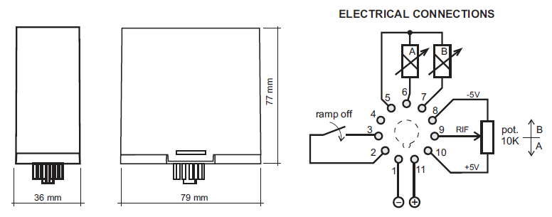
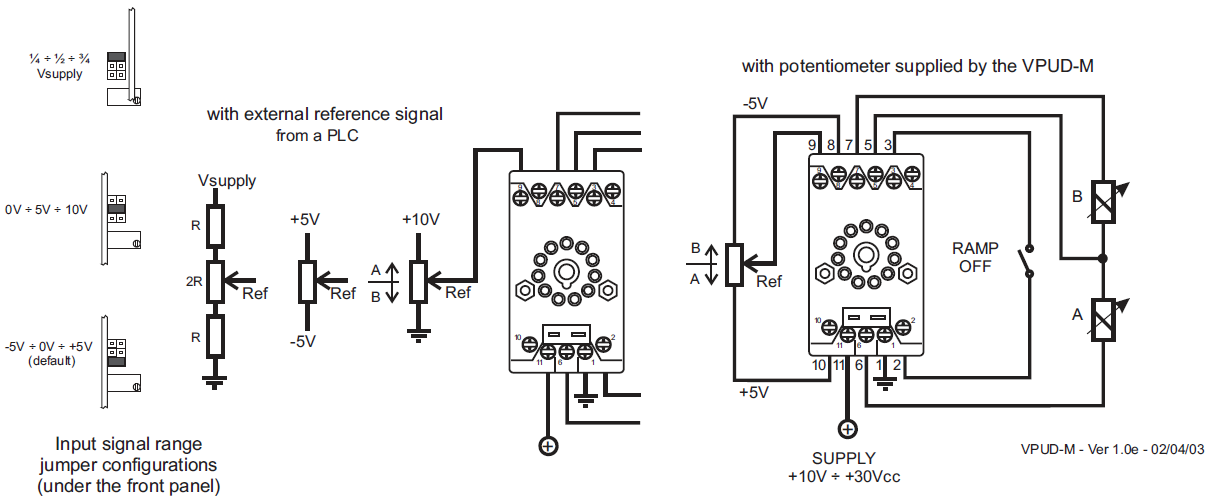
The regulator can be commanded by a potentiometer (the supply voltage ±5V are present) but 0 to 10V or¼ ÷ ¾ Vsupply signals can be utilised (coupling with a PLC). Outputs cannot be active contemporaneously, interlocked by a control circuit.
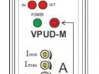
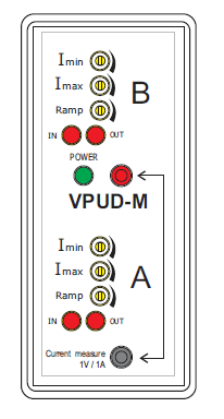
Minimum (BIAS) and maximum (GAIN) currents and rise/fall ramps are independently adjustable. Ramps are adjustable (between 0.1 and 5 seconds) and disabled by a positive signal connected to the proper input terminal. Red LEDs on panel show input signals variation and current variation to the solenoids, signalling if he output circuit is interrupted.
The regulator is protected against voltage reversal and out put short circuits.
 |
Working
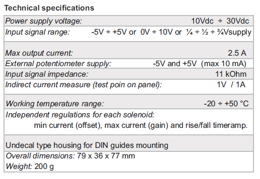
The VPUD-M electronic regulator is calibrated during factory tests with 24V DC supply voltage for 24 ohm proportional solenoids with 200mAminimum current and 750mAmaximum current.Working frequency of PWMoutput is calibrated to 120 Hz.
Ramp trimmers are calibrated to zero (ramp time to zero).
The input reference signal range is set by default from -5V to +5V with 0V as rest voltage value.
When the reference voltage is in its rest value (0V), solenoids are both OFF. When reference signal increases compared to rest value, only "A" solenoid is ON; when reference signal decreases compared to rest value, only "B" solenoid is ON; the two solenoids cannot be contemporaneously ON.
The calibration of regulator can be adjusted for adapting to different solenoids (different supply voltage, etc.) and optimize solenoids working.
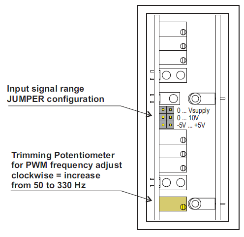
The regulator can be coupled to MAS010 manipulator (reference signal between 0V and +10V with rest value at +5V) or equivalent device. It is necessary to shift the jumper placed under the undecal box panel (see picture).
Opening the panel the frequency working potentiometer can be accessed. The calibration of this parameter can be set by skilled technician.
Each green LED on panel (IN) lights on progressively while reference signal shifts from rest value to both sides. Red LED lights (OUT) show solenoids current, decreasing intensity with current increasing. Variation can be more or less clear, depending on supply voltage. For good working, when current increases, red LEDs should not be completely OFF(100% PWM).
Current calibration
For best performances of proportional solenoid valve calibrate the minimum current (Imin) trimmer so that the valve opens as soon as the red LED switches ON.
Calibrate the maximum current (Imax) trimmer so that the valve is completely open only when reference signal is at full travel.
CAREFUL: Imin and Imax calibrations are not independent. Changing the one it could be necessary to adjust the other.
 |
Ramps calibration
Rise and fall time of current for each solenoid is adjustable with potentiometers. Maximum adjustable time is about 6 seconds going from minimum current value to maximum current value.
Ramps can be disabled temporaneously by 3 terminal input (if potentiometers are calibrated to minimum value, no effect is produced).
Troubleshooting
If one green LED is ON (reference signal is present) and the coupled red LED is OFF, check the correct working of proportional solenoid (failure?) and correct wiring connection.
 |