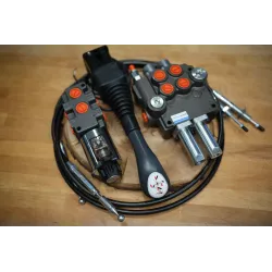


Electronic regulator for PWM controlled, proportional solenoid valves.
STU-PWM electronic card is a regulator for proportional solenoid valves, which can drive up to 8 modules (8+8 PWM outputs), starting from analog inputs (input signal range from 0 to 5V). If the inputs analog signals are generated from potentiometric joysticks, the control card provides a stabilized 5V supply to power them.
Inputs
- n° 8 analog inputs signals (range from 0 to 5V);
- n° 1 enable input defined as CONTROL PANEL ON;
- n° 2 ENABLE inputs with different operating features;
- n° 1 input to select LOW/HIGH SPEED(optional);
- n° 3 ON/OFF inputs, directly carried to three power outputs;
Outputs
- n° 8+8 PWM outputs, to drive proportional solenoid valves (a pair of outputs for each analog inputs);
- n° 1 DUMP VALVE output drived by all manoeuvres;
- n° 1 FAULT output;
- n. 3 ON/OFF outputs, directly drived by three ON/OFF inputs (max 2.5A);
Features
Adjustable PWM frequency, min/max output currents and rise/fall time ramps. As option, STU-PWM is available with two selectable maximum speed sets (LOW/HIGH SPEED), to operate a different maximum speed in different operating conditions.
It is also available a DUMP VALVE output that is turned on when a manouvre turns on. This output has a programmable delay on switch off, to avoid elevated pressure spikes in the hydraulic circuit.
The control unit provides three ON/OFF input/output to drive directly solenoid valves, starting from low power command signal.
To ensure more safety during working mode, the electronic card provides:
- programmable deadband, electrical stroke and adjustable signal threshold;
- an overall relay, feedback controlled, supply all control unit's outputs;
- three inputs ENABLE signals (CONTROL PANEL ON, ENABLE1 and ENABLE2);
- an output to control the DUMP VALVE;
- an output (FAULT) to drive a warning light or a relay that report errors on analog inputs.
Technical specification:
 |
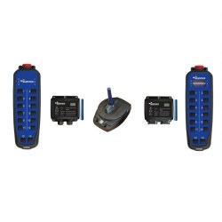
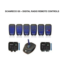
G5-canbus radio command system with ROCKET FLEX TX.
 |
HCU Configuration:
- The Rocket Flex control unit (HCU) has 14 push button with one step.
- The Rocket F. HCU is powered automatically when a button is pushed.
- Rocket F. HCU is prevented to start on E-stop activation only, but after that it is necessary to push a button.
- The turns off automatically after 10s if not used.
- Batteries included.
Cu Configuration:
- DV1: output not available.
- DV2: positive output when PCU is switched-on (max 2A).
- LOOP1 IN-OUT: MOSFET polarized contact, closed when
PCU is ON (max. 2.7A).
- LOOP2 IN-OUT: MOSFET polarized contact, closed when
PCU is ON (max. 2.7A)
- Power supply 9-36Vdc
General information:
- Working frequency: 2.4 GHz.
- For all other radio remote control information, see
the "User manual".
CAN bus configuration:
- Node-ID: 100.
- Speed: 250 Kbps - Slave.
- Terminator: non present.
- LED management via CAN activated.
- CAN filter activated.
- Ignore CAN controller Errors.
- TPDO1 not activated.
- TPDO2 activated.
- TPDO3 not activated.
- TPDO4 activated.
CAN-VIEW display:
Display shows current plane's inclination in both directions (X and Y). It also indicate if the plane is horizontal.
 |
 |
Looking for a non-standard product?
We are able to prepare a customized solution especially for you.