Electronic regulator for PWM controlled, proportional solenoid valves
 |
Electronic regulator for PWM controlled, proportional solenoid valves
Description
STU-PWM electronic card is a regulator for proportional solenoid valves, which can drive up to 8 modules (8+8 PWM outputs), starting from analog inputs (input signal range from 0 to 5V). If the inputs analog signals are generated from potentiometric joysticks, the control card provides a stabilized 5V supply to power them.
Inputs
- n° 8 analog inputs signals (range from 0 to 5V);
- n° 1 enable input defined asCONTROLPANELON;
- n° 2 ENABLE inputs with different operating features;
- n° 1 input to select LOW/HIGH SPEED(optional);
- n° 3 ON/OFF inputs, directly carried to three power outputs;
Outputs
- n° 8+8PWMoutputs, to drive proportional solenoid valves (a pair of outputs for each analog inputs);
- n° 1DUMPVALVEoutput drived by all manoeuvres;
- n° 1 FAULToutput;
- n. 3 ON/OFF outputs, directly drived by three ON/OFF inputs (max 2.5A);
Features
AdjustablePWMfrequency, min/max output currents and rise/fall time ramps.As option, STU-PWM is available with two selectable maximum speed sets (LOW/HIGH SPEED), to operate a different maximum speed in different operating conditions.
It is also available a DUMP VALVE output that is turned on when a manouvre turns on. This output has a programmable delay on switch off, to avoid elevated pressure spikes in the hydraulic circuit.
The control unit provides three ON/OFF input/output to drive directly solenoid valves, starting from low power command signal.
To ensure more safety during working mode, the electronic card provides:
- programmable deadband, electrical stroke and adjustable signal threshold;
- an overall relay, feedback controlled, supply all control unit's outputs;
- three inputs ENABLE signals (CONTROLPANELON, ENABLE1 and ENABLE2);
- an output to control theDUMPVALVE;
- an output (FAULT) to drive a warning light or a relay that report errors on analog inputs.
 |
 |
 |
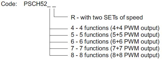
Ordering codes for STU-PWM control unit (connector not included):
 |
56 way female connector ordering code: PCVF56 (protection cover, crimping terminals and taps included)
Technical specification
| Power supply voltage | 10Vdc ÷ 30Vdc (inner 5x20 8A fuse type F8A) |
| Current absorption | 300 mA + load outputs (max 7.5A) |
| Supply for external potentiometers | +5V - max current 50 mA |
| Working temperature range | -20 ÷ +70 °C |
| PWM minimun current range | from 100 to 2500 mA |
| PWM maximun current range | from 100 to 2500 mA |
| PWM frequency | 50-60-70-85-100-125-150-200-250-300 Hz |
| ON/OFF outputs maximum current | 2500 mA (700 mA for FAULT output) |
| Analog inputs impedance | 11 KOhm towards 2.5V |
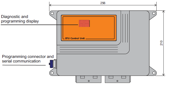
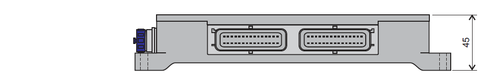
| Overall dimensions with connector mounted | 256 x 210 x 45 mm |
| Drill interaxis | 242 x 142 mm (n. 4 holes of 6 mm diameter) |