
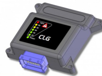
Load limiter for crane
CLG-J Load limiter is an electronic device able to control the load of the crane (or another machine) through two pressure transducer which they are read independently. Then, CLG-J limits the operations that would cause an overloading and/or an overturning of the machine, acting on the bypass valve.


Features
Power supply range: from 10Vdc, up to 30Vdc.
Connector FCI, 24 ways, IP68, mechanical polarization, easy locking cam.
Maximum output current supply: 3A
According to EN 954-1 Safety Standards: Category 2
Two different working areas with two different load limits.
Fast and easy programming sequence
Human machine interface
The green led on the board, in normal operation mode, is lighten to show the power supply.
When faults are present, the green led blinks following a particular sequence related to the fault reasons. (look at the last page for a detailed blinking sequence meaning).
Also, it is present a LED bargraph to show the load percentage in real time, compared to the maximum load. When the load exceedes the 100% of the limit, red LED of the bargraph blinks.
Leds placed into the emergency button box (red colour and yellow colour), are lighted in the following situations:
-
When emergency button is pressed, the red and the yellow blink together.
-
When the load exceedes the 90% of the limit, yellow led is ON.
-
When the load exceedes the 100% of the limit, red led is ON.
The CLG-J load limiter is able to control a Bar LED in order to signal when load exceed the 90% and 100% of maximum permitted load.
For this purpose, it is necessary open the box of secondary emergency push button and connect a cable as instructed below.

Inputs
-
RESET FROM PUSH BUTTON: That input allows the load limiter to power the valve DV for a short period, even if the load value exceedes the load limit, for main boom or for jib if enabled. During this time, the user is able to move the machine in order to return into a safety position. Working conditions are not monitored when reset functionality is enabled, user is responsible for possible machine damage.
-
RESET FROM MAIN BOOM: it is the same RESET as above, but it has been cabled in order to be connect to the main boom descent manoeuvre.
-
RESET FROM JIB: it is the same RESET as above, but it has been cabled in order to be connect to the jib retract manoeuvre.
-
MAIN BOOM PRESSURE transducer input: 4÷20 mA analog input for main boom.
-
JIB PRESSURE transducer input: 4÷20 mA analog input for optional jib.
-
INPUT DV: It allows to connect the load limiter to a remote control in a safety way.
-
DIFFERENT POWER SUPPLY for powered outputs, which includes a disconnect relay with feedback control. Emergency button can be connected to this input.
-
JIB DISABLED: if the crane has not the jib, it's possible to disable the second transducer detection and management by turning on this input.
Outputs
-
Powered output to drive bypass valve coil. The board implements a feedback current control on the mentioned output.
-
Two powered output to drive external optional lamps. The mentioned outputs are driven as well as the leds into emergency button box (90% and 100%).
Setting thresholds
The load limiter's thresholds are programmed using an external, little, 4 buttons, keyboard. The keyboard is an optional. Its name is "PRG-CLG". When it is connected the green led blinks four times in a second.
PC connection
In most cases, CLG load limiter doesn't need to be connected to PC:
-
thresholds are programmed by means of PRG 2 keyboard
-
fault analysis is done by means of the green LED placed near connector
It is possible to connect CLG card to PC with serial port using the special serial adapter AISM (code: PISPM) and free SepSim Windows® program.
PC connection is required in the following cases:
-
to set whole the load limiter's parameters
-
upload/download the working configuration
-
to monitor some working parameters when fault occurs
-
to update the firmware


-
Plug the FCI connector and lock it. Plug the CLG control unit to the cabling.
-
Check the right connection of the dump valve.
-
Check the main boom sensor connection and the jib sensor connection, if present.
-
Check that the emergency button is released.
-
Power the control unit up.
-
When the green LED of the control unit is on (no blinking), then uncover the sheath that protects the connector and pull out the hidden microfit connector.
-
By plugging the keyboard to the microfit connector, the red LED starts to flash one time per second; in case there are not errors or faults, the CLG green LED will start to blinking four times per seconds.
Now, please, follow the simple steps reported here below. It is a quick reference guide to set the load limit thresholds.
STEP 1: SET THE ZERO POSITION


STEP 2: SET THE LOAD LIMIT FOR THE MAIN BOOM


STEP 3: SET THE LOAD LIMIT FOR JIB


STEP 4: SAVING PARAMETERS
