Ramp generator - Product selection guide
What is it for
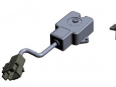
The VRG ramp generator commands progressively a proportional actuator, both in acceleration and deceleration, from a digital command (on/off) or a push-button command.
VRG is available with three types of output:
- PWM A+B (to command directly solenoid valves).
- analogue signal (eg: 0÷5V÷10V or 0.5÷2.5V÷4.5V or 0÷10V on both sides and directional on/off).
- ratiometric signal (for Danfoss modules).
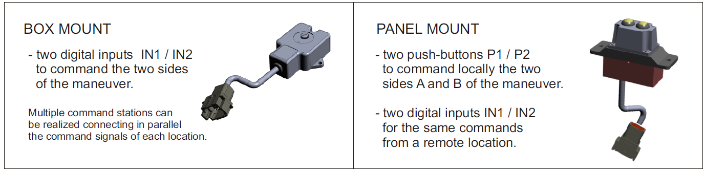
Two configurations available
 |
How it works
Commands can arrive to the VRG indifferently from digital inputs or from onboard push-buttons (panel version).
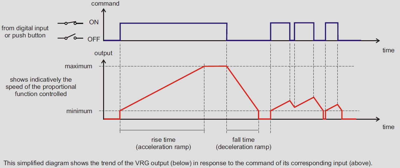
When "side A" is commanded (by IN1 input or by P1 button) starting from rest position, the output moves gradually to the max value set, following a linear acceleration ramp of the duration set, then remains fix to the max value until the command is kept.
When the command is released the output descends towards the minimum value with the deceleration ramp set.
Commands for "side B" work the same way, but using instead digital input IN2 and push-button P2.
 |
The output can command only one side at a time: one side can be activated only when the ramp of the other side has finished. When only a single side is needed a single input/push-button can be used, ignoring the other.
The output varies between minimum and maximum value, according the the acceleration/deceleration ramps set.
Output can assume in stable way only the maximum value (see the "incremental mode" option if you need intermediate stable values). The duration of ramps is settable from 0.1s to 25.5s in steps of 0.1s.
The VRG version with analogue output signal has two additional digital outputs. These indicate the side of the manoeuvre in progress. They are used when a unidirectional output signal has been chosen (eg: 0÷10V for both sides).
These outputs are available also for PWM panel version (using just buttons as commands).
Incremental control feature
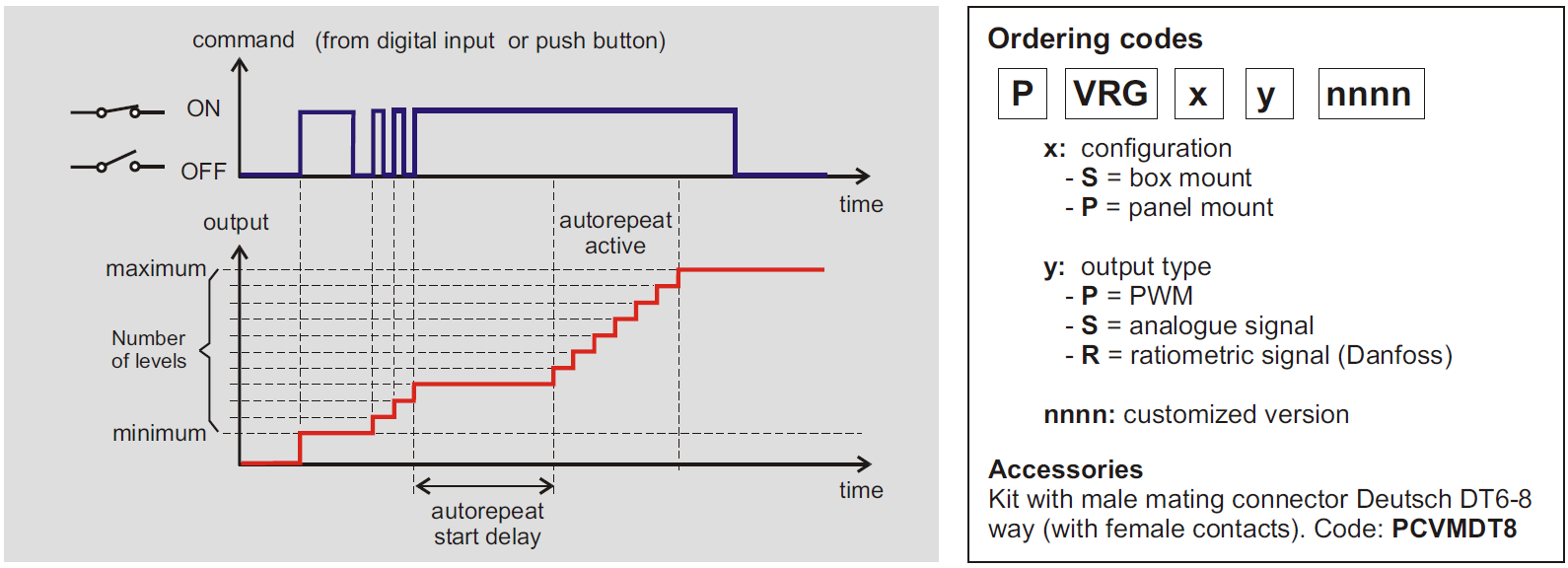
The VRG can be configured to work in "incremental mode" (or "step mode"). With this operating mode the output can be adjusted and remain stable at any of the levels defined, between the minimum and maximum, that have been set.
The number of output levels can be set from 2 to 127, for each side of the maneuver.
When this operating mode is choosen, digital inputs and push-buttons change completely their function: they are no more used to activate side A and side B. They are now used to increase/decrease the output level, step by step.
The function of push-buttons (P1 increment / P2 decrement) is exchanged when you command side B.
Transitions between levels can be smoothed by adding ramps.
Optional functions
The AUTO-REPEAT function is automatically activated when a command is held longer than 0.5s. This is useful, when the output is set with many levels, to approach more quickly to the desired value.
Auto-repeat ctivation delay (default = 0.5s) and repetition speed are configurable.
The MEMORY function (configurable), remember the last output value used to restore it the next working session.
Working example in "incremental mode"
 |
Connections
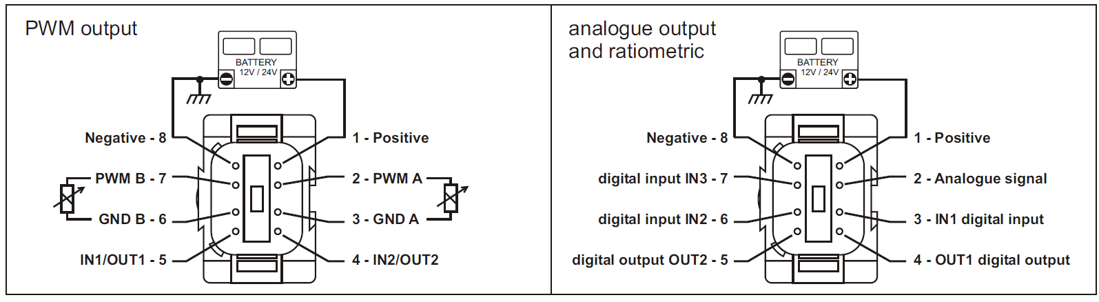 |
Technical specifications
| Supply voltage | 10 ÷ 30 Vdc |
| Operative temperature | -40 ÷ +70 °C |
| Output range (min/max) | PWM: 50÷2500 mA / signal: 0÷10V / ratiometric: 25÷50÷75 % of Vsupply |
| PWM frequencies available | 50, 60, 70, 85, 100, 125, 150, 200, 250, 300 Hz |
| Digital input thresholds | High > 3V / Low < 2V |
| Digital outputs max current | 2000 mA |
| Connections | cable L=20 cm with Deutsch DT04-8 connector |
| Environmental protection degree | IP67 |